Να στείλετε μήνυμα
Σπίτι
Προϊόντα
Περίπου εμείς
Γύρος εργοστασίων
Ποιοτικός έλεγχος
Μας ελάτε σε επαφή με
Ζητήστε ένα απόσπασμα
Ειδήσεις
guangqing(anhui)gas technologies co.,ltd.

Πωλήσεις & Υποστήριξη:

Αρχική Σελίδα ΠροϊόνταΜέρη συστημάτων καυσίμων

Πρότυπες J IMPCO σιλικόνης εξαρτήσεις επισκευής διαφραγμάτων

Κίνα guangqing(anhui)gas technologies co.,ltd. Πιστοποιήσεις
Είμαι Online Chat Now

Πρότυπες J IMPCO σιλικόνης εξαρτήσεις επισκευής διαφραγμάτων

Silicone Diaphragm Model J  IMPCO Repair Kits

Μεγάλες Εικόνας :  Πρότυπες J IMPCO σιλικόνης εξαρτήσεις επισκευής διαφραγμάτων

Λεπτομέρειες:
Τόπος καταγωγής: ΗΠΑ
Μάρκα: IMPCO
Αριθμό μοντέλου: Rk-COBRA
Πληρωμής & Αποστολής Όροι:
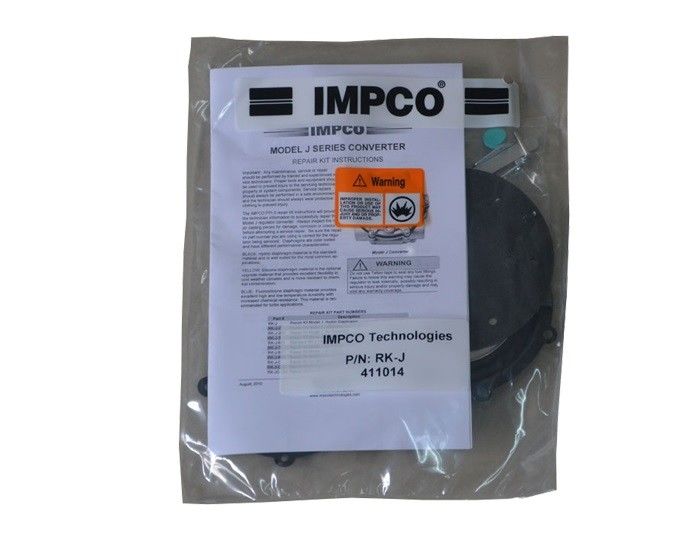
Ποσότητα παραγγελίας min: 24
Τιμή: Depending on quantity
Συσκευασία λεπτομέρειες: Χαρτοκιβώτιο
Χρόνος παράδοσης: 8 εβδομάδες
Όροι πληρωμής: T/T
Δυνατότητα προσφοράς: 1200pcs ανά 8weeks
Λεπτομερής Περιγραφή Προϊόντος
Όνομα προϊόντων: Εξάρτηση επισκευής αριθμός μερών: Rk-j-2
Εμπορικό σήμα: IMPCO Διάφραγμα: Σιλικόνη (κίτρινη)
Υψηλό φως:

Εξαρτήσεις επισκευής διαφραγμάτων IMPCO σιλικόνης

,

Πρότυπες εξαρτήσεις επισκευής J IMPCO

IMPCO RK-J-2 , Model J Converter Repair Kit , Yellow Coded Diapragm
 
The IMPCO RK-J-2 repair kit will provide
the technician information to successfully repair the
Model J converter. Always inspect the major casting pieces for damage, corrosion or cracks before attempting a service repair. Be sure the repair kit part number you are using is correct for the regulator being serviced. Diaphragms is yellow - silicone diaphragm material is the optional upgrade material that provides excellent flexibility in cold weather climates and is more resistant to chemical contamination.
 
 
Πρότυπες J IMPCO σιλικόνης εξαρτήσεις επισκευής διαφραγμάτων 0
 
REBUILD INSTRUCTIONS
Πρότυπες J IMPCO σιλικόνης εξαρτήσεις επισκευής διαφραγμάτων 1
1. Under normal conditions, installation of a complete Model J Repair Kit should be necessary only at the time of a major engine overhaul or when the converter has been out of service for an extended period of time. Each kit includes the necessary gaskets, diaphragms, seals and some replacement screws.
Πρότυπες J IMPCO σιλικόνης εξαρτήσεις επισκευής διαφραγμάτων 2
 
2. Remove the 6 screws (2) from the secondary cover assembly (3).
NOTE: Identify type and location of screws removed (i.e. Torx) to ensure the same type and size screws are returned to the correct locations during reassembly.
Πρότυπες J IMPCO σιλικόνης εξαρτήσεις επισκευής διαφραγμάτων 3
3. Loosen the secondary cover (3) by tapping around the circumference with a plastic screw driver handle.
 
Πρότυπες J IMPCO σιλικόνης εξαρτήσεις επισκευής διαφραγμάτων 4
4. Remove the secondary cover (3) and secondary dia-phragm (4) as a unit. Note the secondary lever (6) pro-truding through the metal tab slot of the secondary dia-phragm. Slide the cover and diaphragm toward the gas inlet to free the lever from the slotted tab of the dia-phragm. Take care not to bend the lever.
Πρότυπες J IMPCO σιλικόνης εξαρτήσεις επισκευής διαφραγμάτων 5
5. Remove the screw (5) retaining the secondary lever fulcrum pin.
 
Πρότυπες J IMPCO σιλικόνης εξαρτήσεις επισκευής διαφραγμάτων 6
6. Remove the secondary lever (6) and fulcrum pin (7). Set aside fulcrum pin for reassembly. Remove the secondary spring (9).
Πρότυπες J IMPCO σιλικόνης εξαρτήσεις επισκευής διαφραγμάτων 7
7. Turn the converter over. Remove the seven screws (20) and lift off the primary cover (19).
 
Πρότυπες J IMPCO σιλικόνης εξαρτήσεις επισκευής διαφραγμάτων 8
8. Remove the primary diaphragm (18).
Πρότυπες J IMPCO σιλικόνης εξαρτήσεις επισκευής διαφραγμάτων 9
9. Remove the primary valve pin (17) and spring (16).
 
Πρότυπες J IMPCO σιλικόνης εξαρτήσεις επισκευής διαφραγμάτων 10
10. Remove plate (14) and the gasket (13).
Πρότυπες J IMPCO σιλικόνης εξαρτήσεις επισκευής διαφραγμάτων 11
11. Remove the gasket (13) from the plate (14). Clean plate as needed to ensure a good seal with a new gas-ket.
Πρότυπες J IMPCO σιλικόνης εξαρτήσεις επισκευής διαφραγμάτων 12
12. Remove the primary seat (12). Clean covers (3, 14, & 19), body (10) and all other metal parts as necessary with a safety solvent as needed and allow to dry prior to reassembly. Do not use harsh solvents such as brake or carburetor cleaner on any of the non-metallic components as they will damage the material.
Πρότυπες J IMPCO σιλικόνης εξαρτήσεις επισκευής διαφραγμάτων 13
13. Install new primary seat (12).
 
Πρότυπες J IMPCO σιλικόνης εξαρτήσεις επισκευής διαφραγμάτων 14
14. Set new plate gasket (13) on the plate (14). The pri-mary pressure hole in the gasket must line up with the hole in the body cover plate as noted in the photo at left.
Πρότυπες J IMPCO σιλικόνης εξαρτήσεις επισκευής διαφραγμάτων 15
15. Place the plate (14) and gasket (13) on to the body (10) and align the screw holes.
Πρότυπες J IMPCO σιλικόνης εξαρτήσεις επισκευής διαφραγμάτων 16
16. Insert the new primary valve pin (17) through the spring (16) and insert into the plate (14) with the larger diame-ter end of the spring resting against the plate.
Πρότυπες J IMPCO σιλικόνης εξαρτήσεις επισκευής διαφραγμάτων 17
17. Set the primary diaphragm (18) in place on the plate (14). Line up the screw holes to the plate.
 
Πρότυπες J IMPCO σιλικόνης εξαρτήσεις επισκευής διαφραγμάτων 18
18. Carefully place the primary cover (19) over the dia-phragm (18). Hand-thread the screws (20) through the cover and plate (14) into the converter body (10).
 
Πρότυπες J IMPCO σιλικόνης εξαρτήσεις επισκευής διαφραγμάτων 19
19. Tighten the screws (20) to 37-43 in-lb. (4.2-4.9 N•m) in a criss-cross pattern.
 
Πρότυπες J IMPCO σιλικόνης εξαρτήσεις επισκευής διαφραγμάτων 20
20. Assemble the new secondary seat (8) and new sec-ondary lever (6) by inserting the seat retaining tip to the end opening of the lever as shown. Be sure the new seat properly locks into place.
 
Πρότυπες J IMPCO σιλικόνης εξαρτήσεις επισκευής διαφραγμάτων 21
21. Position the secondary spring (9) in place on the body (10). Place the secondary lever assembly (6 & 8) into place over the spring (9).
Πρότυπες J IMPCO σιλικόνης εξαρτήσεις επισκευής διαφραγμάτων 22
22. Hold the lever assembly (6 & 8) with the fulcrum pin (7) in place in its locating groove and fasten in place with the retaining screw (5).
Πρότυπες J IMPCO σιλικόνης εξαρτήσεις επισκευής διαφραγμάτων 23
23. Tighten the screw (5) to 29-35 in.lbs. (3.3-4.0 N•m).
 
Πρότυπες J IMPCO σιλικόνης εξαρτήσεις επισκευής διαφραγμάτων 24
24. The end of the secondary lever (6) should be 1/32" be-low the level of the body casting (10). Use a straight edge to measure. Remove and gently bend the lever if necessary to obtain the correct height.
 
NOTE: Bending the lever while installed may result in damage to the seat (8). Remove the lever from the body, bend, reinstall, and then re-check the height.
Πρότυπες J IMPCO σιλικόνης εξαρτήσεις επισκευής διαφραγμάτων 25
25. Align the secondary diaphragm (4) to the secondary lever (6) as shown. The end of the lever must protrude through the tab slot on the bottom of the new dia-phragm (4) after installation. The gap from which the link is punched should be located toward the gas inlet.
 
Πρότυπες J IMPCO σιλικόνης εξαρτήσεις επισκευής διαφραγμάτων 26
26. Install the secondary cover (3) with the six screws (2).
 
Πρότυπες J IMPCO σιλικόνης εξαρτήσεις επισκευής διαφραγμάτων 27
27. Tighten the screws (2) in a crisscross pattern to 29-35 in-lb. (3.3-4.0 N•m), to complete the installation of the repair kit components.
 
Πρότυπες J IMPCO σιλικόνης εξαρτήσεις επισκευής διαφραγμάτων 28
28. Attach a 100 psi air pressure hose to the regulator "IN-LET" fitting.
Πρότυπες J IMPCO σιλικόνης εξαρτήσεις επισκευής διαφραγμάτων 29
29. For models with a primer button: Depress the primer button several times. Air flow should be detected when the primer is depressed.
NOTE: Not all models include a primer button. Skip this step for models without a primer button.
 
Πρότυπες J IMPCO σιλικόνης εξαρτήσεις επισκευής διαφραγμάτων 30
30. Check the primary cover for leaks using liquid leak de-tector solution.
 
Πρότυπες J IMPCO σιλικόνης εξαρτήσεις επισκευής διαφραγμάτων 31
31. Make sure one of the regulator's secondary outlets is plugged. Draw a bubble of leak solution over the other regulator outlet. The bubble should hold for several se-conds when the regulator is pressurized. If any leaks are found, the regulator must be replaced. If no leaks are found, the regulator can be reinstalled and returned to service.
Πρότυπες J IMPCO σιλικόνης εξαρτήσεις επισκευής διαφραγμάτων 32
 

Στοιχεία επικοινωνίας
guangqing(anhui)gas technologies co.,ltd.

Υπεύθυνος Επικοινωνίας: Mrs. Carrie Liu

Τηλ.:: +86 13855195806

Φαξ: 86-551-63664756

Στείλετε το ερώτημά σας απευθείας σε εμάς (0 / 3000)

Άλλα προϊόντα